25+ closed loop control system examples with block diagram
A menu is hidden or shown. A key is pressed or released when the control has keyboard focus.

L298n Based Dc Motor Pwm Control System Design
This is a simplified control circuit diagram for the DSC Series.

. In addition CBCGPGlobalUtilsScaleByDPICBCGPVisualContainer container has a new optional parameter bScaleFonts TRUE by default. A control gains or loses focus. The main intention of this device is to maintain the engine speed constant by changing the steam supply to the engine.
Whereas positive feedback tends to lead to instability via exponential growth oscillation or chaotic behavior negative. Automatic switch to backup power 4-pin single separation- eg. It is used in a continuous feedback loop in order to maintain the speed accuracy at 1 or less.
Introduction to control systems 1. Lets now move towards a simple example regarding the working of a simple PID controller using Simulink. Wiring diagram - surge protective device SPD.
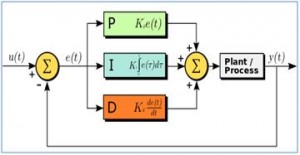
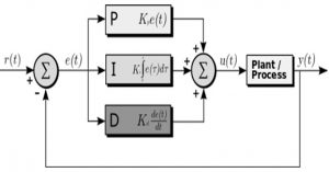
As the name suggests PID algorithm consists of three basic coefficients. Top 5 Control Engineering articles April 25 to May 1 2022. 8212017 1 Hareesha N G Dept of Aero Engg DSCE Blore 2.
Lots of functions block. A control is resized or moved. A block diagram of a PID controller in a feedback loop rt is the desired process value or set point.
PID controller design using Simulink MATLAB. We also use a half-wave rectifier. The PID toolset in LabVIEW and the ease of use of these VIs is also.
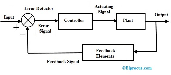
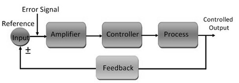
In closed-loop control the control action from the controller is dependent on the process output. Concept of automatic controls Open loop and closed loop systems Concepts of feedback systems Requirements of an ideal control system Types of controllers Proportional Integral Proportional Integral Proportional Integral Differential controllers. The block diagram of a simple PID controller is provided in the figure below Figure 2.
The user requests help eg. Fortunately this is unlikely if the inner loop is inherently faster than the outer loop or the tuning forces it to be. A widget is disposed.
You can see we use a TRIAC to control the voltage. By pressing the F1 key Key. Cascade control block diagram.
Automatic washing machine Immersion rod. Proportional integral and derivative which are varied to get optimal response. In a nutshell block is techie jargon for sleep.
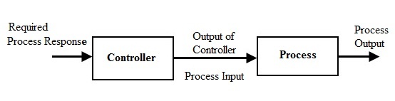
Open loop control System. Dimensions of the inverter. Negative feedback or balancing feedback occurs when some function of the output of a system process or mechanism is fed back in a manner that tends to reduce the fluctuations in the output whether caused by changes in the input or by other disturbances.
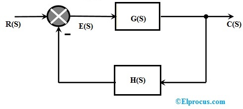
A closed-loop control system is a system in which control action is dependent on the desired. For anyone thats interested this is the control circuit diagram with more details. The two controllers might compete with each other to the point of driving the closed-loop system unstable.
Simplify the block diagram shown in Figure 3-42. Grid and system protection - eg. The best examples of control systems are.
An elevator control system is an example of sequence control. Then eliminating two loops results in Figure 3-43b. The summing point can either add signals together in which a Plus symbol is used showing the device to be a summer used for positive feedback or it can subtract signals from each other in which case a Minus symbol is used.
What happened is that it called recvfrom there was no data and so recvfrom is said to block that is sleep there until some data arrives. The first control system was invented by James Watts Flyball governor in the year 17. The symbol used to represent a summing point in closed-loop systems block-diagram is that of a circle with two crossed lines as shown.
First move the branch point of the path involving HI outside the loop involving H as shown in Figure 3-43a. Closed loop systems the theory of classical PID and the effects of tuning a closed loop control system are discussed in this paper. At present the control system plays an essential role in modern technology because these systems will affect our daily lifeless or more.
Implemented ability to prevent diagram fonts text formats scaling when the diagram is being scaled. Closed loop control System. Simplify the block diagram shown in Figure 3-13.
A new method EnableScalingFonts added to CBCGPVisualContainer class. Often based on system logic that involves system states. Changing the speed of the car is one of the best examples.
An open-loop control system is a system in which the control action is independent of the desired output signalExamples. Combining two blocks into one gives Figure 3-33c. Fronius Symo GEN24.
Automatic switch to backup power 4-pin double separation with ext. You probably noticed that when you run listener above it just sits there until a packet arrives. 4 What is open loop and control loop systems.
Closed Loop Control System Block Diagram Types Its Applications

Pdf Pso Tuned Pid Controller For Controlling Camera Position In Uav Using 2 Axis Gimbal
Solved Consider The System Represented By The Block Diagram Of The Following Figure The Closed Loop Transfer Function T S Y S R S Is Select Course Hero
On Off Control System Control System System Math

Understanding A Process Control Loop Process Control Control Engineering Studying Math

What Is The Difference Between An Open Circuit And A Short Circuit Quora
Open Loop Closed Loop Control System And Their Differences

Pdf Pso Tuned Pid Controller For Controlling Camera Position In Uav Using 2 Axis Gimbal
Solved Consider The System Represented By The Block Diagram Of The Following Figure The Closed Loop Transfer Function T S Y S R S Is Select Course Hero

Open Loop Closed Loop Control System And Their Differences
What Are The Basic Three Objectives Of Any Control System Quora
Pid Controller Working Types Advantages Its Applications
Pid Controller Working Types Advantages Its Applications
Closed Loop Control System Block Diagram Types Its Applications
Open Loop Closed Loop Control System And Their Differences
Solved Find The Error Transfer Function E S R S Of The System Whose Block Diagram Is Given What Should K Be For The Steady State Error To Be Course Hero

Control System In Mechatronics Open Loop Closed Loop Control System Mechatronics Control Variable Control System